

Vibration Campaign
DuthSat successfully completed the required vibration tests. Testings were conducted in the premises of the Hellenic Aerospace Industry (HAI-corp) in Athens,Greece.
Test-POD
The testpod used in testings designed and constructed in Xanthi, Greece. The test-POD is constructed from aluminium 7075; helicoil screw-holes are installed in all interfaces.


Overview of the test-POD design
Test-POD and DUTHSat on top of the LDS vibration system at HAI
Test Set-up
The vibration table used for the DUTHSat Vibration Testing is an LDS-LING Dynamic System Vibration model V804MKII, by Brüel & Kjær, which is located at the premises of the Hellenic Aerospace Industry (HAI). This is controlled by an LDS DVC 4000 Digital Vibration Controller and a DSC 8 Digital Sine Controller. The LDS DVC 4000 Digital Vibration Controller, the DSC 8 Digital Sine Controller and the LDS Vibration Test System have recently been calibrated, and their calibration certificate was up to date at the time of the test.

The LDS DVC 4000 Digital Vibration Controller
Test sequence
1. Z-axis
1.1. Resonance survey (Z-1)
1.2. Quasi-static (sine burst) Z
1.3. Sinusoidal vibration Z
1.4. Random vibration Z
1.5. Resonance survey (Z-2)
2. X-axis
2.1. Resonance survey (X-1)
2.2. Quasi-static (Sine burst) X
2.3. Sinusoidal vibration X
2.4. Random vibration X
2.5. Resonance survey (X-2)
3. Y-axis
3.1. Resonance survey (Y-1)
3.2. Quasi-static (sine burst) Y
3.3. Sinusoidal vibration Y
3.4. Random vibration Y
3.5. Resonance survey (Y-2)
The sequence of the Vibration tests is as follows (in the order that the tests were performed):
Test Performed
Static Loads
A sine-burst test was used to apply a quasi-static load to the CubeSat inside the test-POD in order to strength qualify the item and its design for flight. The sine-burst test is a simple method to apply a quasi-static load using a vibration shaker and shock testing software. This is used in lieu of acceleration (centrifuge) or static tests.The applied loads are at 10.8g for each axis.
Modal Survey
The Modal survey was conducted with the CubeSat being integrated into the test-POD described above, which was attached to an absolute rigid base. A Modal survey test was run before and after running a test at full level, in order to compare the results of the Modal survey tests, and to identify a change in CubeSat integrity due to settling or possible damage.
Sine Vibration
The Sine Vibration Test was conducted according to the specifications of the QB50 System Requirements. After the test there was no noticeable effects or anomalies of DUTHSat GR01, as measured by the Resonance Survey tests.

The test input versus frequency for the Sine Vibration test
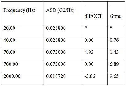
Random Vibration
The Random Vibration Test was conducted according to the specifications the QB50 System Requirements. After the test there was no noticeable effects or anomalies in the performace of DUTHSat GR01, as measured by the Resonance Survey tests.
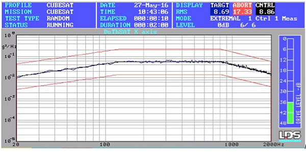
The accelerometer Response. Similar results were obtained for the Y and Z axes.
Thermal-Vaccum Campaign
Bake out
The beak out tests took place in May 6,2016 at the premises of the NATIONAL CENTER FOR SCIENTIFIC RESEARCH "DEMOKRITOS". Duration of the tests was about 5 hours.


The thermal-vacuum chamber and the interior of the chamber including DUTHSat in its TVAC fixture

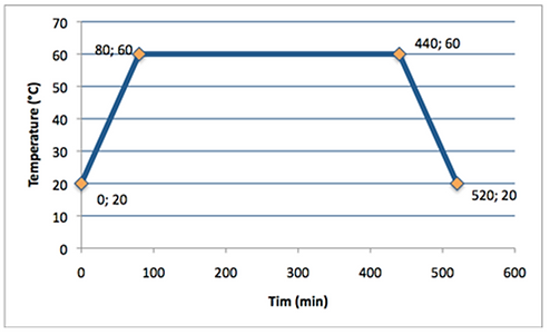
The temperature profile during the test
The total duration of the bake-out test was 4.5 hours. Out of this period, the temperature was kept at 50oC from minute 80 to minute 260, or for a total duration of 180 minutes or 3 hours after thermal stabilization. Pressure was maintained at 10-5 mbar for the entire duration of the test
Thermal-Vaccum Test (TVAC)
The thermal-vacuum tests took place in May 7,2016 at the premises of the NATIONAL CENTER FOR SCIENTIFIC RESEARCH "DEMOKRITOS". Duration of the tests was about 7.68 hours.

The measured temperature profiles versus time along the thermo-vacuum cycling. The times when the TCF tests were performed are also indicated. Thermistor 2 was located in the +Y side (blue line) and Thermistor 1 was located in the -Y side (red line).
Battery Pack Flight Acceptance Test
The following tests are required for Lithium-Ion cells and battery packs to determine if they are acceptable for flight to the ISS.
Electrochemical Characteristics
-
Measurement of Open Circuit Voltage: Measure the Open Circuit Voltage (OCV) using a multimeter and record the value for each of the cells/ batteries. Measurements should be recorded with 0.1 V precision.
-
Measurement of Closed Circuit Voltage: Ensure that the cell/ battery is at least charged to 4.0V before proceeding. After setting up the programmable load to a constant current of 1.875A, load the battery and wait for 30 seconds before recording the Closed Circuit Voltage.
Charge Cycling Data Procedures
The Charge Cycling Data Procedures include the following cycles in this order: Charge, Discharge, Charge, Discharge, and Charge. Record relevant data for all of these cycles. The temperatures for these cycles should also be recorded and a 10-minute rest period should be provided between charge and discharge.
-
Charge the cells/ batteries to 4.2V using a current of C/2. Then hold the batteries at a constant 4.2V until the current drops below 50mA.
-
Discharge the battery pack at a rate of C/2 until the voltage drops to 3.0V.
-
Repeat charge cycling procedures until cycling is complete.
Note: If the MOSFET does not reset for any of the following procedures, discard the cells.


Upper an lower side of the programmable load board used for discharging the batteries

Charge-Discharge cycle procedure
Cell Overcharge Procedures
-
Overcharge cells/ batteries to 5.0V with a current of 1C.
-
Record the voltage at which the protection activates and the MOSFET opens the circuit.
-
Discharge the cells/ batteries at a rate of C/5 and record the voltage at which MOSFET closes the circuit.
-
Complete a charge/ discharge cycle and record the capacity.
Cell Overdischarge Procedures
-
Overdischarge the cells/ batteries at a rate of 1C to 0V.
-
Record the voltage at which the MOSFET opens the circuit.
-
Charge the pack at rate of C/5 and record the voltage at which the MOSFET resets itself.
-
Complete a charge/ discharge cycle and record the capacity.
External Battery Short Procedures
Externally short the circuit pack using a 10 milliOhm load and hold it for three hours (recording the temperature of the battery every 5 minutes). Record the current at a rate greater than 1 kHz for the first three seconds of the test, and record the current at the time the MOSFET disconnects the circuit.
After the External Short procedure, charge the cells/ batteries at C/5 current to determine the voltage at which the MOSFET resets itself. The pack should then go through one discharge/ charge cycle. Record the capacity.
Vibration Test Procedure
Record the OCV for each cell/ battery before vibration testing and between each axis of vibration. Vibration testing should follow the following spectrum for one minute on each axis.
Discharge/ charge/ discharge cycle each battery after the vibration tests and record the capacity. The pass/ fail criteria requires that there shall be less than 0.1% change in the OCV and less than 5% change in capacity before and after vibration tests and throughout the remainder of the test procedures.
Vacuum Test Procedure
-
The length, width, and height need to be measured before beginning this test. Measurements should be recorded with 0.1mm precision.
-
Obtain and record the mass of each cell/ battery. Measurements should be recorded with 0.1g precision.
-
Measure the voltage of all cells/ batteries and record the values. If any batteries are not fully charged, charge before continuing.
-
Place fully charged batteries into the vacuum chamber at atmospheric pressure and pull vacuum at approximately 8 psi/minute. Maintain vacuum (approximately 0.1 psia) for 6 hours. Re-pressurize the chamber to ambient at a rate of 9 psi/minute.
-
Visually inspect the batteries for leaks, deformations, or bulges. Record any findings.
-
Obtain measurements of the length, width, and height of the post-vacuum tested batteries.
-
Obtain and record the mass of each cell/ battery. The pass/ fail criteria requires that there is less than 0.1% change in mass.
-
Discharge/ charge/ discharge cycle the cells/ batteries and record the capacity. The pass/ fail criteria requires that there shall be less than 0.1% change in the OCV and less than 5% change in the capacity before and after vacuum testing.

Bakeout Parameters
Bakeout Profile